Take control of your photography with this innovative DSLR remote control featuring STM32F722 MCU.
With the ability to control up to two cameras and an integrated sound or light sensor, capturing the perfect shot has never been easier.
This remote control can even be attached to a fast object sensor or valve sensor, making it the perfect tool for professional photographers and hobbyists alike.
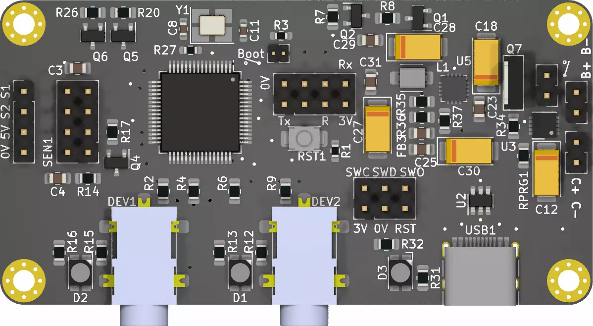
The brain of the new DSLR Remote Control F7 is STM32F722RETx.


DSLR Remote Control F7 PCB Top and Bottom view
This Camera Remote Control was developed to work the New Sensor Generation for DSLR Remote Control
In the slides below
1. Connection towards the Sound & Light Sensor V4. These sensors are controlled with SPI1(CS on PA4, SCK on PA5, MISO on PA6 and MOSI on PA7).
There is an interrupt from AD5235 connected to pin PA3 configured as EXTI3.
The analog signal from sensor is fed to MCU on pin PC4 ADC1_IN14.
The sensor power is controlled using pin PB0 configured as GPIO Output so that we can turn the power off when we are using the Valve Sensor V2 or Fast Object Sensor V2.
2. The MCU is STM32F722RETx
3. Connection toward ESP-01 or ESP8266 using USART3 PC11 as Tx and PC12 as Rx. To reset the ESP module pin PA15 configured as GPIO output is used.
This module is used to send and receive settings to/from an Android phone or tablet that is running the GUI.

4. Internal header connector towards the Valve Sensor V2 and Fast Object Detector Sensor
This header provides 5V power towards the sensors and pins PB8 and PB9 are configured as GPIO output when used with Valve Sensor V2 and EXTI when used with Fast Object Detector Sensor
5. 5V regulator
6. Power switch connector
7. LiPo battery 2S connector - charging set to 500mA by MCP73213
8. External charger connector - 9V
9. 3.5mm jack connectors and LED indicators for DSLR Camera and other devices. They are connected through an opto-insulator (14) IC to pins PC6, PC7, PC8 and PC9 configured as GPIO output.
With them we are controlling the DSLR Focus and Shutter, or if we use a flash or two we can control the flash trigger.
10. Programming header is exposing the following pins: NRST, SWCLK, SWDIO, SWO
11. Power and charger LED
12. USB C connector
13. 3.3V regulator
14. Opto-insulator - there is no electrical connection between DSLR camera or device and the remote control
You can download the KiCAD Project files and STM CubeMX configuration file RemoteF7.ioc
The 3D model in STP format for DSLR Remote Control F7 3D Model is available for download.