High Speed Photography Trigger Circuit
I have successfully used the sound, light/dark triggers with the Canon EOS 450D but you do so entirely at your own risk.
If you have a digital camera made by another manufacturer, check the remote control specifications carefully.
Please make sure you read the laser warnings on your laser device, they can be harmful.
Never point the laser at anyone and never look directly at the laser beam, it can permanently damage your sight.
Please read Liability Disclaimer and License Agreement CAREFULLY
Freezing fast motion objects in a picture (also known as High Speed Photography), can give you some pretty special photographic effects. High Speed Photography is used in sports, physics and more.
In this guide I will describe how to capture fast moving objects using a camera (in my case a Canon EOS 450D aka Rebel XSi & Kiss Digital x2) and a little DIY (Do It Yourself) electronic circuit.
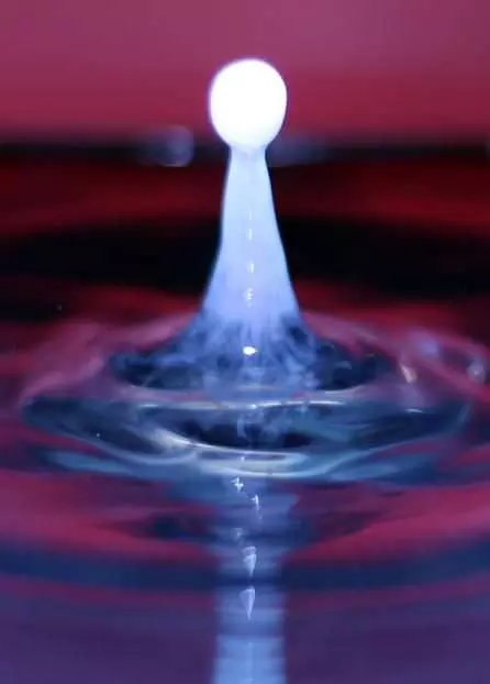
A drop of milk hitting the water captured using Sound trigger
In the picture below is the first attempt to make an Sound, Light/Dark trigger circuit for my camera. The simple trigger circuit is based on a LMV722M as an amplifier/comparator and few transistors. If used as a normal remote (like Canon RS-60E3) you have 3 buttons available: focus, shutter and bulb. I think these don’t need any explanation. Used as a triggered remote the circuit reveal a new world for you to explore.
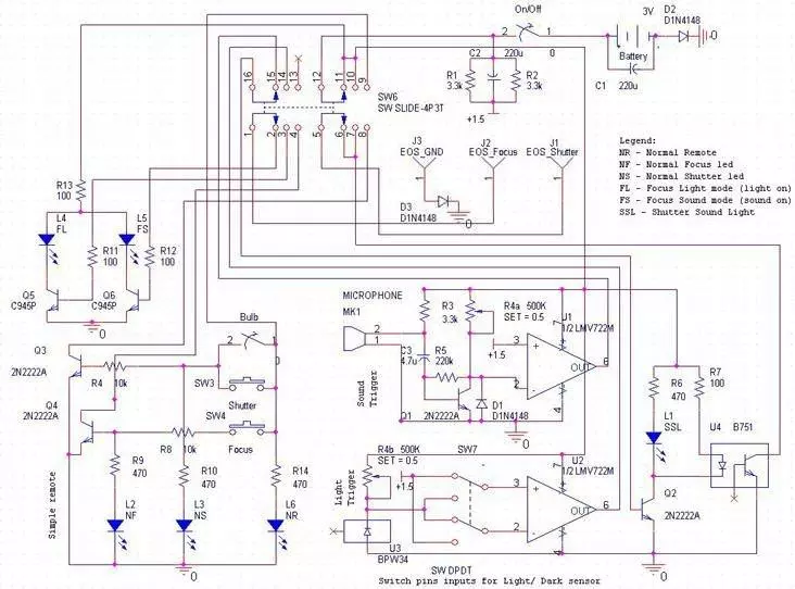
After a while I realized that the sound trigger is not sensitive enough and the trigger signal generated by the sound/dark trigger needs to be delayed to actually get the picture of the event…so I redesign the circuit and the result is presented below.
The Delay Circuit
When the switch Sensor/Normal Remote is in the “Normal” position the first part of the circuit is a simple wire extension of the camera shutter button. The Focus push button is used to focus the camera (Focus Indicator LED is lit) and the Shutter is used to take the picture (Shutter Indicator LED is lit). In case you need to use long exposures you can use the Bulb switch.
You can download the delay circuit file from here. To create the circuit I used EAGLE Light Edition (Is FREE) software that can be downloaded from here.
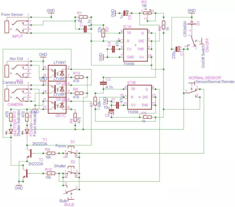
When the switch is used in “Sensor” position the buttons mentioned above are deactivated and only the shutter circuit is closed when the circuit is trigger, so you need to put your lenses focus switch in manual position.
The delay circuit shown uses a TS556 timer, an IC consisting of two 555 timers. Grounding the input starts the first timer and produces a square pulse at pin 5. The width of the pulse is determined by the capacitor 1μF and the setting of the 1MΩ variable resistor.
The output from pin 5 is coupled to the trigger pin 8 of the second timer through a 4.7nF capacitor. When the output from pin 5 falls to zero, the second timer starts, producing a 10ms pulse at output pin 9. This pulse gates the 2N2222A to close the circuit of camera shutter through the LTV847 optocoupler. Output 5 can also be used to gate an SCR/transistor in order to provide auxiliary trigger to an flash unit/camera. To adjust the time delay rotate the slider of variable resistor.
t[s] = 1.1*C[F]*R[Ω] so the smallest delay provided by this circuit is given by
1kΩ resistor in series with 1MΩ of variable resistor (when this one is set to 0)
t=1.1*0.000001*1000=0.0011s=1.1ms
If 1MΩ is set to maximum value then t=1.1*0.000001*(1000000+1000) =1.1011s.
The Sound Trigger
This circuit is used to trigger the camera when a sound is detected. The 1MOhm variable resistor in series with the 2.2kΩ gives the circuit a gain about 455 that makes this circuit very sensitive. To amplify the signal received from the microphone one half of the LMV722M operational amplifier is used, the other half is used as a comparator. The 100kΩ variable resistor sets the threshold level at which the circuit triggers. This circuit is used to get pictures of popping balloons or champagne bottles. For this trigger the delay circuit must be set to minimum or to an acceptable value (speed of sound is around 343m/s in air) if the sound source is near to sensor.
You can download the Sound Trigger circuit file from here.

The Light/Dark Trigger
This circuit is used to trigger the camera when a beam of light is detected or interrupted. To amplify the signal received from the BPW34 photodiode one half of the LMV722M operational amplifier is used as transimpedanc
e amplifier, the other half is used as a comparator. The 100kΩ variable resistor sets the threshold level at which the circuit triggers. Used in light mode this circuit can be used to trigger when lightning or flash light is detected, in dark mode you can get a water drop splash (the water drop interrupts a beam of light). In this case the delay circuit is use to trigger the camera after the light beam is interrupted – a water drop with a diameter of 3mm will have a speed around 6m/s.
If you don’t like physics then you can set the delay by trial and error.
You can download the Light Dark Trigger circuit file from here.

Cables
To make the connections between triggers and delay circuit and between camera and delay I used shielded stereo cable. To connect the device to camera you will need a 2.5mm stereo male plug for the other connections I used 3.5mm male/female stereo plugs.

Canon EOS 450D Remote Control Plug Pinout
Gear settings
Flash: optical slave and 1/16 output power (the built in flash can be used but the results are...average);
Exposure: 1/160 s or lower depending on the event speed;
ISO: 100-200;
Aperture: f8-f16;
Focus: manual focus.
Next step is framing and focusing. While trying to stay within the best performance on the lens, I either zoom or move the tripod, until I have the desired framing. Focus can be obtained either automatic or manual, but do remember to switch to manual to lock focus.
Examples

Crown of water in led laser light

Crater made by a water drop

Small water column