DIY Reflow Soldering Station: A Comprehensive Overview
Please read Liability Disclaimer and License Agreement CAREFULLY
Warning: Electrical Safety Notice
Before attempting to build or operate the DIY reflow soldering station described in this article, it is imperative to be aware that the hardware operates at 220V AC. Working with high-voltage systems poses inherent risks and demands a thorough understanding of electrical safety precautions.


Introduction:
For electronics enthusiasts seeking a precise and customizable reflow soldering experience, constructing a DIY reflow soldering station is an exciting project. This article provides a detailed overview of the key components and their functionalities, offering a comprehensive guide for building your own soldering station.
Power Supply:
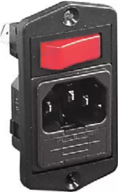
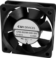
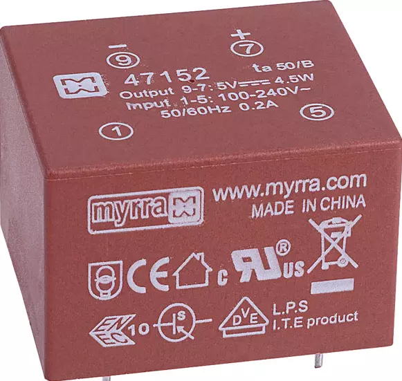
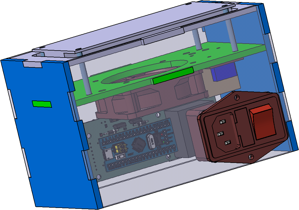
The 220V AC is supplied through the AC Power Entry Module IEC-320 C-14 BVA01/Z0000/02. A Transformer Myrra 47152 steps down the voltage to a crucial 5V, supplying power to essential components such as the BluePill with STM32F302 microcontroller board, fan, and the G3MB-202P 5V DC 1 Channel Solid-State Relay.


User Interface:
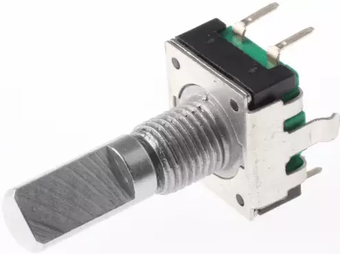
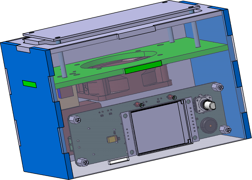
The station features a user-friendly interface displayed on a 1.8" ST7735 LCD. User inputs are facilitated through an encoder PEC11R-4220F-S0024 and an RS PRO 17mm Black Potentiometer Knob for 6mm Shaft with a D-shaped grip, ensuring precise control over the soldering process.

Temperature Control and Cooling:
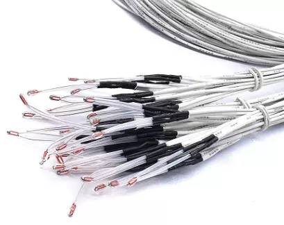
Maintaining optimal temperature is achieved through two strategically positioned 100K ohm 3950 NTC's, calibrated with meticulous accuracy using an FLUKE 51 II Thermometer as a reference. The reflow soldering station incorporates a CFM-6020S-040-320 fan, intelligently activated to cool down the hot plate when needed, ensuring temperature stability.
Operational Modes:
The DIY reflow soldering station offers two distinct modes: rework and reflow. In rework mode, the temperature is kept at a preset value, allowing for precise touch-up soldering. In reflow mode, the temperature follows a preset profile, ideal for soldering components with specific temperature requirements. Both modes utilize a PID controller, ensuring consistent and accurate temperature control throughout the soldering process.
Connections:
The intricate network of connections ensures seamless communication and control within the system. Notable connections include those for SD Card, Encoder, ADC for NTCs, Fan control, Hot plate power control, Buzzer, Encoder button, LCD command, and SPI interface.

Conclusion:
Building your own DIY reflow soldering station offers the satisfaction of creating a precise and reliable tool tailored to your needs. With a robust power supply, intuitive user interface, accurate temperature control, and intelligent cooling, this reflow soldering station provides the necessary features for successful soldering projects. As you embark on this DIY journey, ensure meticulous attention to detail in the assembly and follow safety guidelines to enjoy a versatile and efficient soldering tool for your electronics projects.
The enclosure outline for LASER cutting from 4mm thick acrylic sheet can be downloaded here.
KiCAD Schematic and PCB for controller are available here.
The software for STM32F302 can be downloaded here.
Please note that the PID parameters are generic and you need to change them according to your system, the values are found in Reflow.h file
#define PID_KP 1.0f    /* Proportional = The Temperature to target */
#define PID_KI 0.2f    /* Integral */
#define PID_KD 0.1f    /* Derivative = Speed of temperature change */
#define PID_INT_MAX 1000.0f  /* Maximum value for integral term */
#define PID_INT_MIN -1000.0f /* Minimum value for integral term */
#define CONTROL_EFFORT_MAX 1000.0f  /* Maximum value for control effort */
#define CONTROL_EFFORT_MIN -1000.0f /* Minimum value for control effort */
The function that handles the PID calculation is
// Function to calculate PID control effort
float calculatePID(float error) {
	// Calculate PID terms
	float proportional = pid.Kp * error;
	pid.integral += pid.Ki * error;
	// Anti-windup for integral term
	if (pid.integral > PID_INT_MAX) {
		pid.integral = PID_INT_MAX;
	} else if (pid.integral < PID_INT_MIN) {
		pid.integral = PID_INT_MIN;
	}
	float derivative = pid.Kd * (error - pid.prevError);
	pid.prevError = error;
	// Calculate and return PID control effort
	float controlEffort = proportional + pid.integral + derivative;
	// Saturate the control effort
	if (controlEffort > CONTROL_EFFORT_MAX) {
		controlEffort = CONTROL_EFFORT_MAX;
	} else if (controlEffort < CONTROL_EFFORT_MIN) {
		controlEffort = CONTROL_EFFORT_MIN;
	}
	return controlEffort;
}
In the file adc.c you need to change the values for NTC and resistors R2 and R3 based on the actual measurements.
//100k NTC measured resistance in Ohms @ 25C
const float R1[2] = {99000.0, 101000.0};
//10k resistor measured resistance in Ohms @ 25C
const float R2[2] = {10440, 10450.0};

Comments powered by CComment