
Mooz 2 - LASER upgrade from 1.6W to 5W
Please read Liability Disclaimer and License Agreement CAREFULLY
This website and the material covered is for informational purposes only.I will take no responsibility for what you do with this knowledge.
I can not be held responsible for any property or medical damages caused by items you read about on this website.

Please wear eye protection before powering the LASER.
OK, after all safety measures are considered let's begin with the items that you will need:
1. LASER that module that has "TTL" control, do a search on Aliexpress or Banggood and buy the one that fits your needs, i would recommend one with 12V power supply
2. Short network cable (or you can sacrifice the one from your printer)
3. 220kOhm.resistor, depending on your soldering skills you can use the the size you are comfortable with. I had 0.25W in my parts so i went with it.
4. Soldering tool and soldering consumables
5. Shrink tubes or insulating tape
(6. Support plate)
Now,let's make the following convention, we count the pins on the RJ45 connector from 1 to 8 as shown in below image.
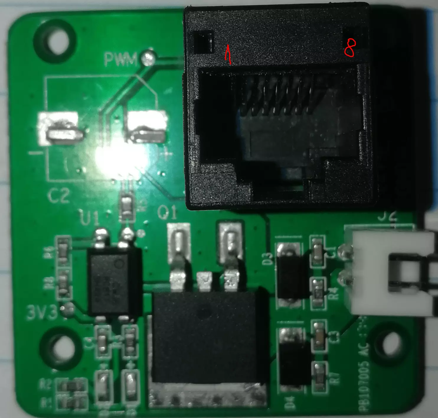
The connector used on cable to connect each module to the printer is RJ45, the golden pads from the image below
represents the shiny metallic pads you see on the connector, the numbering correspond to image above but the color
of the wires will most likely be different in your case.
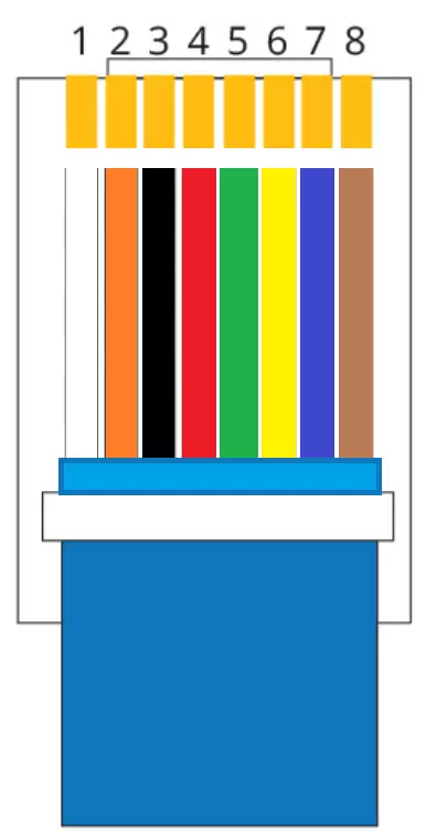
Pins are connected as follows:
1. VCC or +12V - > this connection is not needed if you plan to use an external power supply for your LASER
2. GND or 0V -> this must be connected to the LASER power supply ground if external power supply is used
4. PWM -> this pin is used to control the On/OFF and the LASER power
7+8. Module identification -> connect one end of the 220kOhm resistor to pin 7 and the other end to pin 8
3,5,6 are not used.
I wanted to be able to test if an external power supply makes a difference giving the fact the the printer main board is powering the CNC head,
i noticed that with the LASER i got there is no difference, the board being able to power the laser with no issue.
Assembly steps:
1. Having one extra Mooz cable for the add on modules i decided to cut one end of the cable
2. Strip the cable insulation exposing minimum 10mm of wire (try more or less depending on your skills)
3. Strip the wires insulation 1-2mm and using the soldering tool pre-solderer the wires
4. I used 100mm x 100mm x 4mm aluminium plate as adapter plate, to be able to add and remove the LASER with ease to/from the printer,
so here i have marked the required holes on the plate - 2xM3 for the controller board and 2xM3 for the LASER itself
5. Mount the adapter plate with laser on the printer to have a good estimation of how long the final cables must be
6. Cut the PWM + power extension wires to fit the printer size (in my case i got the wires+connectors labeled PWM and 12V in the image below wit the LASER)
6.1. If you will not get cable extensions with your LASER kit you will have to find a solution to connect pin 4 to PWM signal on the LASER controller and the GND
7. Strip the wire insulation on the PWM and power 1-2mm and pre tin them
8. The LASER might be shipped with a long connection cable from controller, so now is a good opportunity to cut it to size - see right hand side wires
9. Since there is only one GND wire on the cable from the main board i used a "Y" split for the GND just in cas i will use the external power supply
10. Solder pin 2 (GND) wire to GND+GND (black wires from PWM and 12V in the image below) and apply insulaion
11. Solder pin 1 wire (+12V) to the 12V of the LASER and apply insulation
12. Solder pin 4 wire to PWM of the LASER and apply insulation
13. Connect the PWM side of the cable to the PWM connector on the controller board
14. Connect the power side of the cable to the power connector on the controller board
15. Time to put your glasses on. This LASER turn on to full power for a second when power is applied.
Seems that many LASERs from this category are suffering the same issue in different degrees, some are
staying ON till PWM signal is received.
16. Use the laser as a normal MOOZ laser but consider the boost in power when making the G-Code.


On the left side I have insulated 220kOhm resistor soldered between wires 7 and 8.
The "Y" split of the GND (the 2 black wires in the middle) allows me to use the external power supply or the power provided through the cable.

Final assembly of the LASER - i use the adapter plate as heat-sink for the LASER controller

Have a look here Mooz 2 - LASER Post processor for Fusion 360