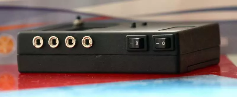
GVI Digital Camera Remote Control
Please read Liability Disclaimer and License Agreement CAREFULLY
I have successfully used the sound and light sensors with the Canon EOS 450D but you do so entirely at your own risk.
If you have a digital camera made by another manufacturer, check the remote control specifications carefully.
If you are using a LASER pointer please make sure you read the laser warnings on your laser device, they can be harmful.
Never point the laser at anyone and never look directly at the laser beam, it can permanently damage your sight.
GVI Digital Camera Remote Control for DSLR camera is a step forward from my High Speed Photography for Canon EOS 450D. This remote is based on AVR Microcontroller ATmega328 and is programmed using Arduino IDE
GVI Digital Camera Remote Control is a tool for photographers to trigger cameras or flashes based on input signals from various sensors - for the moment i use only sound and light inputs, but maybe in the future i will add more sensors.
At this moment the circuits are being tested and the software is in debugging-optimization phase.
Enough talking let's get the facts
The Light Sensor
This light sensor gives you a huge amplification of the signal and can be use to trigger in the dark of night or in the day time (not tested yet in a very sunny day). R1 is used to adjust the sensitivity of the circuit while R2 controls the gain (amplification of the input signal).
The circuit is powered from the remote control via a stereo cable and its small parts count will enable you to insert it in a small case.
Light Sensor Schematic you can download Cadsoft Eagle schematic.
The Sound Sensor
As in the light sensor, the sound sensor one offers you a gain of about 1100 divided on the two stages of the amplifier.
For this one, all credits goes to Audioguru from EDABOARD who basically give me the schematic. Thanks again!
Sound Sensor Schematic you can download Eagle schematic.
And finally, the "brain" of this remote control...i give you the
Central unit
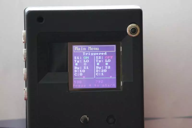
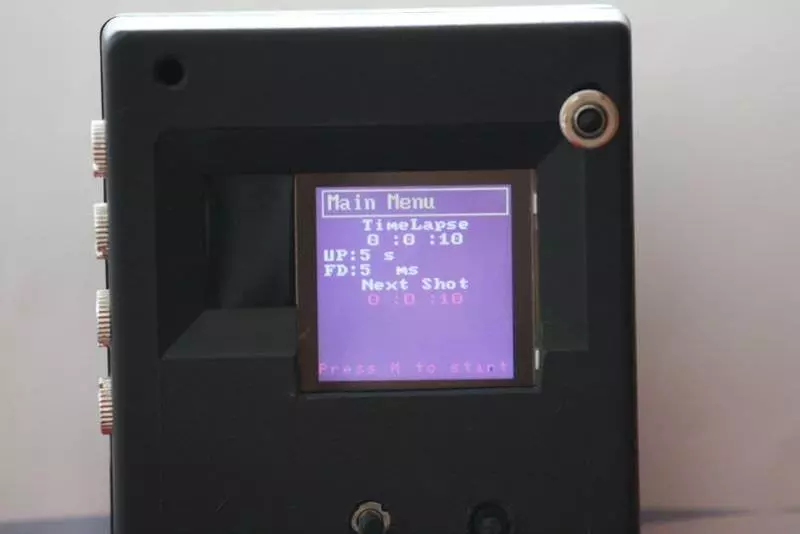
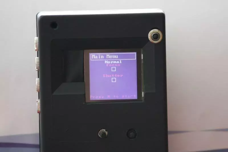
This unit is controlled using a push button (Menu Function) and a Arduino Joystick Switch (Up, Down, Left, Right and Set functions) and the remote control settings values are displayed on an Nokia 6100 display (132x132 12bits GLCD) with Philips controller.
The LCD driver for this controller is based on this documentation can be downloaded from here for Philips PCF8833 controller and here for Epson S1D15G00 controller.
Here you can download Eagle schematic.
To program the ATMEGA328 i've used an Arduino Duemilanove and Arduino-0018 IDE environment and the result is the sketch.
Well, this is it for the moment.
I'll wait your suggestions or features request for this remote and remember, if you decide to build it and use it, you will do it on your own risk.
Below I've uploaded some pictures of the finished remote...till I will find a suitable case.
1. The assembled remote
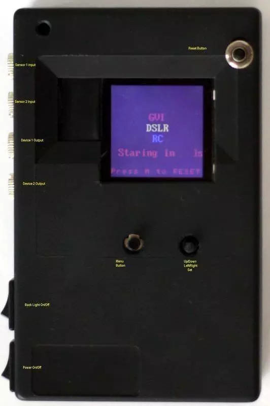
2. Boot/Reset Screen
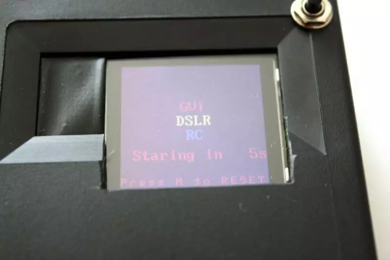
3. Main Menu

4. Triggered Menu
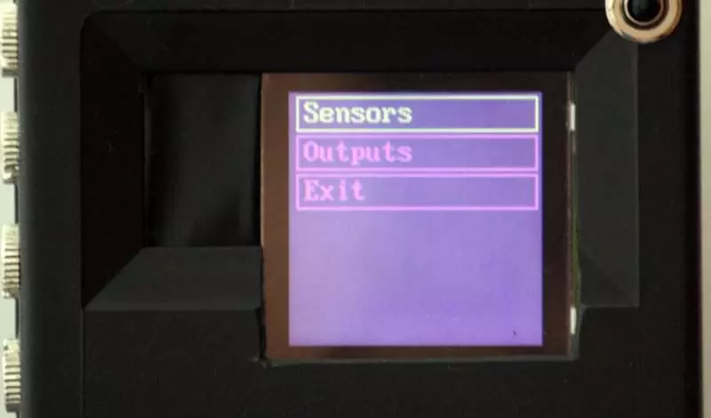
5. Sensors Menu
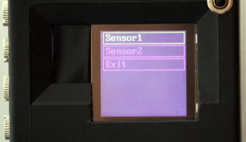
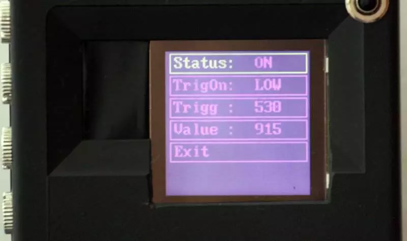
6. Sensor Settings
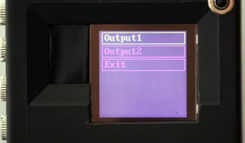
7. Outputs Menu
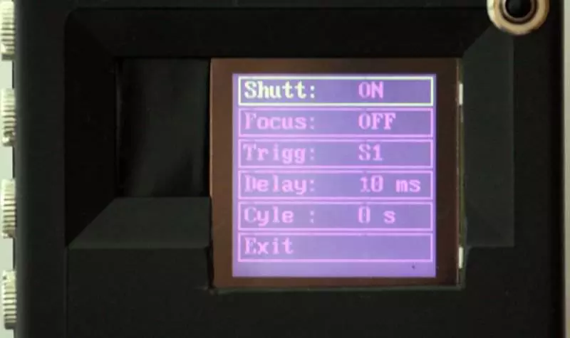
8. Output Settings
9. Timelapse Menu
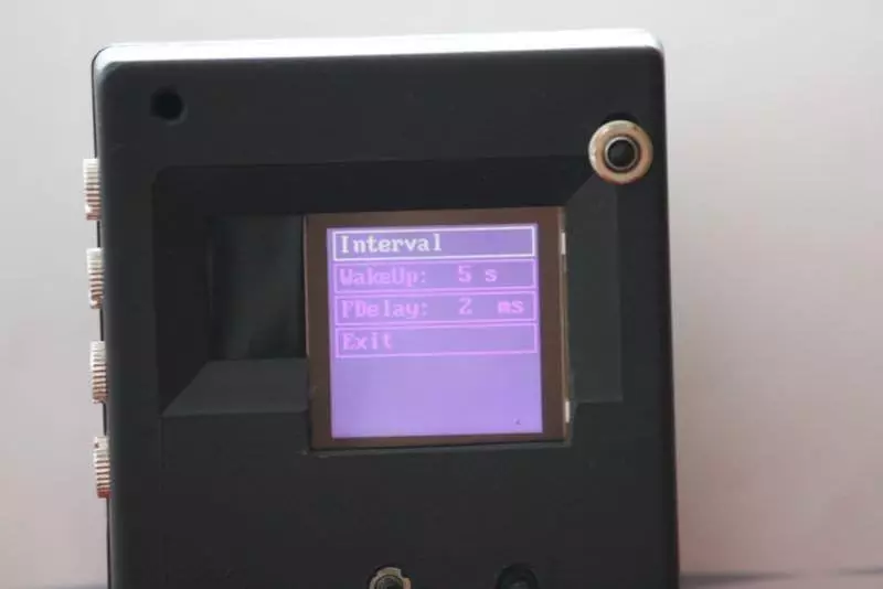
10. Timelapse Settings
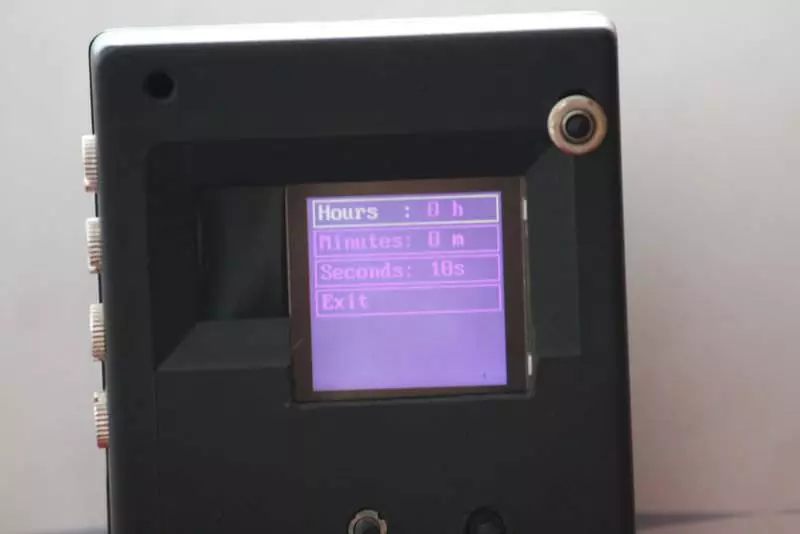
11. LCD Menu
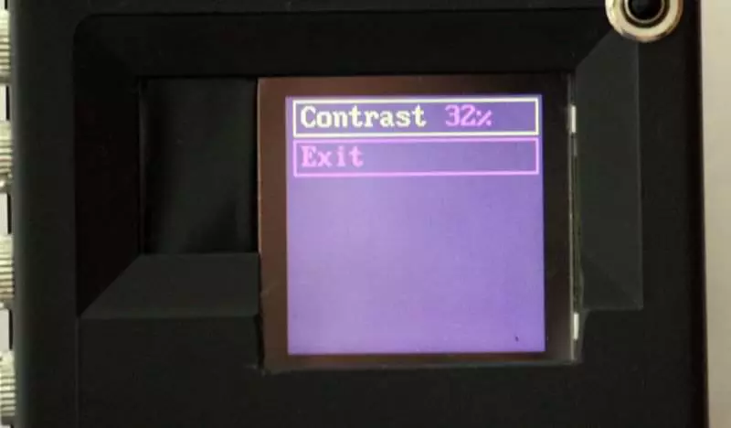
12. Bulb Burst Mode
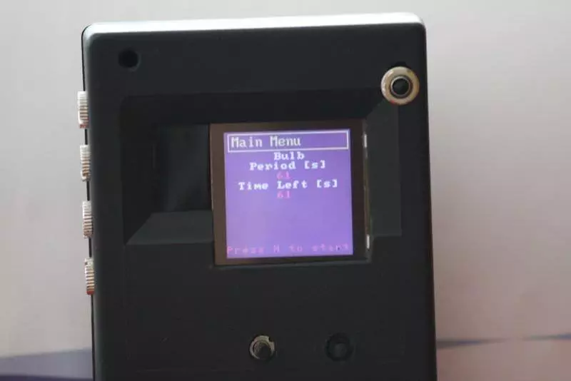
13. Triggered Mode
14. Timelapse Mode
15. Normal Mode
16. Side View
